
and Space Ace
Operation of the conversion card
and Space Ace
Operation of the conversion card
![]()
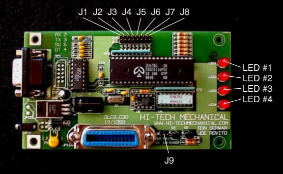
LED Indicators
On the conversion card you will find four red LED indicators. These indicators are used to identify a wide variety of functions. Upon power-up, all four LEDs will light momentarily and as the card initializes they will go through a startup chase sequence six times. After the startup sequence, the board will display the mode that it is running (LD-V1000 or PR-7820) by flashing either LED #1 (LD-V1000) or LED #2 (PR-7820). The startup sequence and mode flash will happen even if the player and mainboard are not plugged in, this indicates that the card is working. After the mode flash all the LEDs will go out. The board is now waiting to get startup commands from the mainboard.
As the card receives commands from the mainboard, LED three will identify the data flow to and from the mainboard and LEDs one and two will identify the dataflow to and from the Sony player. If problems were to occur, LED lighting patterns can help identify the problem.
LED #1 Sony Busy TX– Flashes on startup for LD-V1000 mode
This LED will light after the Sony receives a command from the mainboard and stays lit while the Sony executes the command indicating that the Sony is working (Busy). The Sony will tell the mainboard when it is done (TX) and the LED will go out.LED #2 Sony Ready RX– Flashes on startup for PR-7820 mode
After the Sony completes a command and tells the mainboard that it is done, this LED will light indicating that it is ready to receive another command. It will remain lit until the Sony receives another command from the mainboard (RX).LED #3 Mainboard TX RX (Transmit and Receive)
This LED will light when the mainboard transmits a command (TX) and will wait until it receives a done signal (RX) from the Sony. At this time the LED will go out.LED #4 Mainboard Idle
This LED will light and stay lit while the mainboard is idle meaning that a scene is playing and it will stay lit until the mainboard transmits a command.TX = Transmit RX = Receive
Jumper Settings
The board has nine jumpers. Refer to the board assembly drawing at the top of this page to identify their respective location. Three jumper shunts are included with the kit. You will never need to install more than three jumpers at a time.
J1 When installed, all audio commands will be ignored. Sound will stay on at all times regardless of the attract mode sound settings on the main board.
J2 Not used
J3 Not used
J4 Not used
J5 Not used
J6 Not usedJ7 When installed, the frame index will appear on the display.
J8 Used for RS-232 diagnostics only, DO NOT USE THIS JUMPER.
J9 When installed, the card will operate in the LD-V1000 mode. When not installed, the card will operate in the PR-7820 mode.
All jumper settings will only take affect when the card initializes upon power up. DO NOT attempt to install or uninstall jumpers while the power is on. BE SURE that the card's mode setting (J9) is the same as the mainboard's mode setting (LD-V1000 or PR-7820).
The card is shipped with no jumpers installed; therefore it will operate in the PR-7820 mode.
The Dragon's Lair Project website is not affiliated with "Hi-Tech" or Joe Rovito. D-L-P HOME
| LASER GAMES
| LASER COMMUNITY
| TECH CENTER
|