PIONEER PR-8210 TO PR-8210-A CONVERSION
Written and developed by Andrew Hepburn - 25 March 2002
Photos by Marcel Gonzalez
INTRODUCTION
This document will help you transplant parts from a non-working Pioneer PR-8210-A laserdisc player into
a working PR-8210 player, to convert it to PR-8210-A. The
procedure is fairly simple, and I have done this myself and verified that the modified player works with a Star Rider boardset.
DISCLAIMER
If you are unsure what any of the terms used in this document refer to or do not
understand sections of this document, make sure you find out! Do not
attempt anything in this document unless you know what you are doing! The
information in this document is believed to be correct and works fine for the
author. I cannot guarantee that this will work for you and I am not responsible
for any damage you may cause to your laserdisc players.
PARTS NEEDED
- A non-working Pioneer PR-8210-A player - The problem with the player must be that
it will not spin up or play. If the player does play but does not work with your
Star Rider boardset, then it is not a good candidate for transplanting
and may still not work once the procedure is completed. In that case you may
want to verify that the cause of the problem is not the boardset or the
connection from the boardset to the player. A good resource for asking
questions about Star Rider is the
Dragon's Lair Project Message Board.
- A working PR-8210 player
- A soldering gun/pen, solder, small flat-head screwdriver, Phillips screwdriver, and some patience
IMPORTANT NOTES BEFORE YOU BEGIN
After removing parts from your PR-8210-A player, it may not be possible to go
backwards and put the player back together properly. The reason for this is we
will be cutting and removing the power cord from the PR-8210-A player, which
could prove very difficult to reattach if you change your mind.
It will be necessary to turn the players upside down several times during this
procedure. When turning the players upside down, do so from front to back and not
from side to side. (A player should never be up on its side). It could cause
the laser assembly to slide downwards due to gravity, possibly causing damage to
the player.
The PR-8210 player is missing one hole in its inside metal casing where the
wires for the PR-8210-A connector need to go. In order to provide room for these
wires, it may be necessary to cut a small section of the back of the PR-8210
player above its back connector plate.
When finished, your new player will have two back connector plates. The regular
PR-8210 back connector plate will provide the video and audio as usual, and the
PR-8210-A connector plate will be hanging off the back of the player, and only
the Centronics connector on it will be functional.
If you want to use your PR-8210 player for multiple games (such as M.A.C.H. 3), you
can still use the "remote control" jack on the back of the PR-8210 to control
the player.
There will be other important notes listed throughout this document. Please make
sure you read them carefully and do not proceed unless you understand what they
refer to and the possible damage that could be caused by not following them.
IMPORTANT NOTE ABOUT TESTING THE STAR RIDER BOARDSET
If you are going to be hooking up your Star Rider boardset to a different
monitor or test monitor and you need a composite sync signal, you may not be
able to tie the h-sync and
v-sync directly together from the boardset's monitor
output. If you do this, the player will spin up when you turn
the game on, but all of the laserdisc player tests will fail, and the game will
not start.
After I finished doing this PR-8210 / PR-8210-A conversion, I was testing the
boardset and player with a Commodore monitor. Since the
monitor took in composite sync, I just tied together the h-sync
and v-sync
wires. The player would spin up, but the game would not start nor would any
player tests work. It appeared as though the game could not find the current
frame number. Many weeks later, I was running the boardset through the player
tests, and I lifted the boardset to get at something, and one
of the sync wires accidentally popped off, and suddenly the laserdisc player
tests all started passing. I verified this problem by hooking the sync wires
together and taking them apart, each time watching the player tests fail and
then start passing again.
Click on the pictures for a larger view.
SECTION A - WORKING ON THE PR-8210-A
PREPARATION
The very first thing we will need to do is remove the hinged cover of the
PR-8210-A laserdisc player. We do this first because once we remove the power
cable we can't turn the player on to open the cover.
Turn on the PR-8210-A and press the reject button so that the cover "pops"
open. Lift the cover up. Unplug the player and turn it around so that you are facing
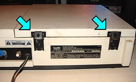
the back of the player. There are two hinges holding the cover on the player. Each
of these hinges has three screws. Remove the screws so that you can
completely remove the cover from the player. IMPORTANT NOTE: The hinges have
fairly powerful springs on them and will fly up forcefully as soon as the last
screw is removed from one. Make sure you are aware of this while removing the
hinge screws.

PART 1 - REMOVING THE PR-8210-A CONNECTOR
Turn the PR-8210-A player upside down.
Remove all screws in the bottom of the player.
Lift the bottom cover off the player.
Inside the player, you will see some PCBs, the laser assembly, the back
connector of the player, and some other miscellaneous electronics.
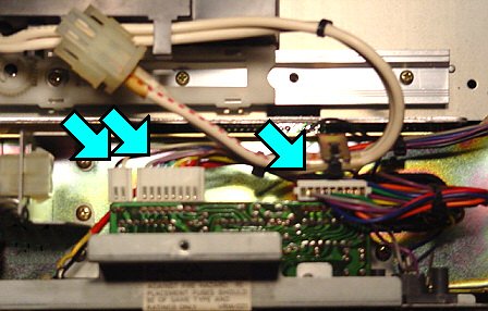
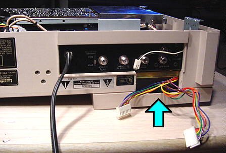
Looking at the Centronics connector on the back of the player, you will notice
it has a small PCB and three plugs. Make a note of where the plugs are
attached so that you can reconnect them later, and then unplug them.
In order to remove the back connector plate from the player, we will need to
disconnect the video plug, audio plugs, and the power cable. We will not be
removing the Centronics connector from the connector plate.
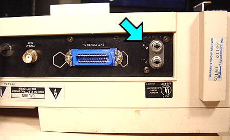
You have two choices to remove the audio and video plugs. You can either cut the
wires going to these plugs, or you can remove them. The audio plugs can be taken
out by removing the screw located in the middle of them. The video plug can be
removed by undoing the nut that secures the plug to the connector. My PR-8210-A
had some rust on the video connector making it difficult to remove, so I just
cut the wires from the inside and left the plug where it was.

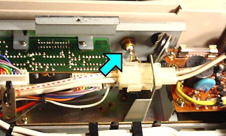
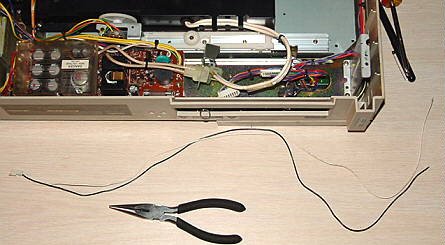
To remove the power cable, cut the cable on the inside of the player. It may be
possible to unsolder the power cable if you want to preserve it; however I found
applying any heat to the power cable pins caused them to come out of the power
board completely.
The back connector plate is now ready to come out of the player freely. Undo the
two screws that hold the connector plate to the player. Take the connector plate
out and place it aside. At this point you can remove the power cable completely
by pulling it through the connector plate or by cutting it off.
PART 2 - REMOVING THE SMALL CONNECTOR PLUG
We will need to lift up the large PCB in the player to remove some of the
wiring that the Centronics connector uses. The large PCB pivots at the front of
the player and is held down by screws around the edge. Remove the screws
holding down the large PCB and lift it up. It may be helpful to use something to
hold the board up while you work. A long piece of tape works nicely.
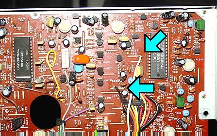
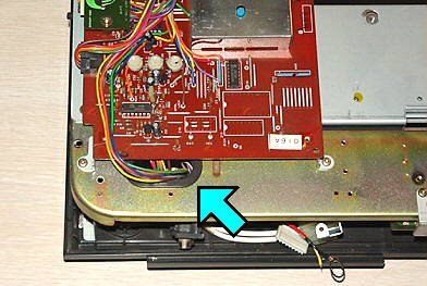
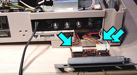
If you examine the three plugs that were attached to the Centronics connector,
two are large and one is small. The small plug should have a black wire and a
white wire coming out of it. If you follow these two wires through the inside of
the player, you will notice that they are soldered to two places on the large
PCB that we lifted up.
Examine the large PCB where the wires are connected and write down the
locations of the wires. It may be helpful to draw yourself a small picture of
where the wires are connected. This information is important as we will need to
refer to it when reconnecting the wires.
The locations on the large PCB where the black and white wires are
connected should not have any components. They should
just be two pieces of metal going through the PCB.
Desolder the two wires from the large PCB. We now want to remove the two
wires and small plug from the player. Carefully pull the wires out of the
player. You may have to cut a few of the wire-wraps in order to remove them. Do
not cut the black and white wire. Once you have removed the small plug and
wires, place them aside.
PART 3 - REMOVING THE "BRAIN" OF THE PR-8210-A
This part will require removing the top cover of the player. In my opinion,
removing the top cover is the most difficult part of this procedure. In order to
remove the top cover, we will need to remove some screws from inside the player
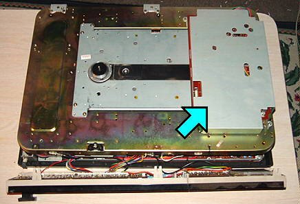
first. If you look inside the player on the extreme right, you will notice a "U"
shaped bracket on its side with two screws at the bottom. These screws hold the
top cover of the player. Remove the screws. There may also be another bracket on
this side that also holds the top cover. There may also be additional screws on
this side that hold the front panel to the top of the player.
Put the bottom cover back on the player and put a few of the screws back in it. This
stops the player from falling to pieces when you take off the top cover.
Turn the player right side up again so that it is facing you. The center spindle
of the player will have a plastic black ring around it. Pry this ring off using
a small screwdriver.
You will see three screws under the ring. Remove these
screws. Remove all the other screws you see in the disc section of the
player.
The top cover is now ready to come off the player. Start by putting your
fingers under the sides of the player, then carefully lift the sides to separate
the sides from the player. The front panel of the player is also connected to
the top cover by plastic tabs. Carefully remove the front panel from the top
cover.
Now you should be able to completely lift the top cover off the player.
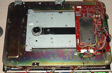
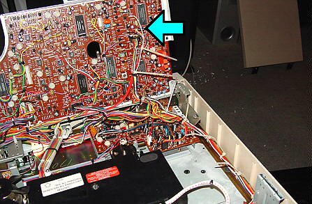
On the right side of the player, you will see a metal cover that covers the
"brain" board.
Undo the screws on the cover and take it off.
IMPORTANT NOTE: Now that the board is exposed, examine the board for three
plastic pots on the board. You should take great care not to touch these
pots. Even brushing them with your hand can cause them to turn. These pots control how
the player finds the start and end of a disc.

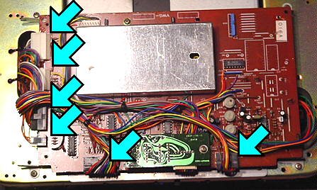
At the back of the board, you will notice a bunch of wires going through a hole
in the metal casing of the player. These wires are for the two large plugs we
removed from the Centronics connector. The wires are connected to various places
on the board. Carefully pull the wires up through the hole.
The board will also have various other plugs attached to it. Write down the
locations of these plugs as we will need to reconnect them later. After that,
remove all the plugs.
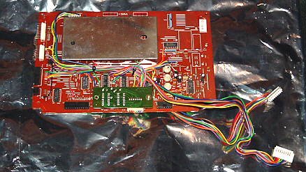
Undo the screws holding the board to the player, remove it, and place it aside.
Congratulations! We are now finished working with the PR-8210-A. Whatever you do
with this player after this is up to you. I recommend saving the player in case
you need any parts from it to fix another player.
SECTION B - WORKING ON THE PR-8210
PREPARATION
Follow the same preparation instructions as you did for the PR-8210-A. We will
need to have the disc cover removed before starting. At all times during this
section of the procedure, take great care that you do not accidentally touch or
damage the laser lens on the PR-8210, as it will now be exposed. You do not want
to end up with two non-working players.
PART 1 - ADDING THE SMALL CONNECTOR PLUG
The first thing we will do in adding the PR-8210-A connector to the PR-8210 is to
put in the small plug that has the black and white wire on it.
Turn the PR-8210 player upside down.
Remove the screws in the bottom of the player.
Lift the bottom cover off the player.
Follow the instruction in Part 2 of working on the PR-8210-A to lift up the large
PCB inside the player.
Next we will solder the black and white wires to the proper locations. Examine
the large PCB and find the proper locations for the black wire and white wire of
the small plug using the information you recorded before you removed them from
the PR-8210-A. I've found that the pieces of metal where you want to solder these
wires do not hold solder very well. In order to make it easier to attach these
wires, use a small flat screwdriver and slide it under the metal pieces where we
want to attach the wires. GENTLY pry the metal pieces up SLIGHTLY; just enough
so that we can wrap the wires around the metal pieces. You may have to strip the
wires a little so that you can slide the wire under the metal pieces and then
wrap it around them. After you have secured the wires, place a small amount of
solder on the wires to make sure they cannot slip off.
Lay the two wires through the inside of the player so that the plug is coming
out of the player. You may want to secure them to wires that already exist in
the player using new wire wraps. This will stop them from moving around in the
player and getting caught in other internal electronics.
PART 2 - REPLACING THE "BRAIN" OF THE PR-8210
Follow the instructions in Part 3 of working on the PR-8210-A to remove the top
cover of the PR-8210. Remember to first take out the screws from inside the
player that hold the top cover on. When finished, you should have the player
right side up with the top cover off. Turn the player so that you are facing the
back of it.
Remove the metal plate that covers the brain board of the player. As mentioned
in the PR-8210-A section, take great care not to accidentally touch or move the
plastic pots. Even though we will be taking out the existing brain board, you
never know when you might need it in the future to repair another player.
Examine the plugs attached to the brain board and verify that they are the same
as what you wrote down when examining the plugs on the brain board for the
PR-8210-A. The only difference should be the lack of wires coming off the back of
the board for the two larger PR-8210-A connector plugs.
Remove the plugs from the brain board. Undo the screws on the board and take it
out. Take the brain board from the PR-8210-A and put it in the player. It should
be orientated so that the plugs you took off match up. Screw the new brain board
in place. Reattach all the plugs, referring to your notes on where these plugs
should be attached.
Replace the metal cover for the brain board. Since there is no hole in the metal
casing for the PR-8210, all wires for the two PR-8210-A connectors will
just be hanging off the back of the player.
We will now need to put the top cover back on the PR-8210. As mentioned in the
important notes section at the beginning of this document, we will need to make
some room on the back of the cover for the PR-8210-A wires. If we replace the top
cover as-is, these wires may get badly squished and could even get
damaged. Instead, cut out a small section of the cover above the left side of the back
connector. I used a drill to make a few holes in the
plastic until there was a large enough gap for the wires to fit through
comfortably.
IMPORTANT NOTE: At this point there are three new plugs coming out of the
PR-8210; one small plug and two larger plugs. DO NOT turn on the PR-8210 unless
these plugs are attached to the PR-8210-A connector. Doing so will cause the
player to fast-forward as soon as it is turned on and start "banging" the laser
assembly once it reaches the end and cannot go any further.
Once you have put the top back on the PR-8210 and attached the plugs to the
PR-8210-A Centronics connector, turn the player on and play a laserdisc
to make sure it is operational. You will now be ready to test the player with
your Star Rider boardset!